Thursday, August 1, 2013

TRANSFORMER


1.       Transformers Transformation Ratio
          
       V1/V2=N1/N2=I1/I2=K or NS/NP=VS/VP=IP/IS=K

2.       Explain the function of Buchholzs Relay for Transformer protection?

It is the gas and oil operated relay. It has two circuits, on is trip and second is alarm. Any minor fault develops that time the evaporated gas will actuate the alarm circuit; otherwise any major fault rush of oil will actuate the Trip Circuit.

3.       What are the protections for Transformers?

a)      Buchholzs relay
b)      Overheated relay
c)       Earth fault relay
d)      Temperature sensor

For higher transformer additionally

a)      Restricted Earth fault relay
b)      Differential relay


4.       How to check Transformer oil? What should be value?

a)      To collect oil from bottom drain in Test kit.
b)      Adjust Test kit spears (2.5mm or 4mm)
c)       Increase the voltage gradually up to tripping point

The oil should withstand 30KV for 1 minute gap with a gap of 2.5mm

5.       What is the breather? Details about the Silica gel

It is a small container, contains silica gel and oil. It absorbs the moisture from the atmospheric air and allow the fresh air to the conservator.

6.       What is C.T. and P.T.

C.T. is Current Transformer which step down the current. It is used for current measurement and protection.P.T. is Transformer Tap changing on HT side. Transformer is working at mutual induction action.


1.       YPM of Transformer

a)      Obtain the work permit
b)      Transfer the load to the other transformer
c)       Switch “ON” the Earth Switch on primary and secondary side
d)      Physically clean the Transformer
e)      Check the insulation resistance of primary and secondary winding and check the winding resistance
f)       Check the terminal tightness
g)      Check the Earth connections of Transformer
h)      Carry out B.D.V. test of Transformer oil
i)        Control box cleaned with contact cleaner
j)        Check the Silica gel
k)      Check the HT and LT bushings
l)        Open the Earth switch
m)    Energize the Transformer an d give load
n)      Close the permit.

2.       Which are the Paralleling conditions of Transformers?

a)      Voltage must be same as check tap-changer position
b)      Frequency must be same
c)       Phase sequence must be same
d)      Impedance of both the Transformers has to be same
e)      Vector group of both must be same.


MOTORS


1.       What is the slip of an induction motor at the time of start?

A.      100%.

2.       What is the protection against single phasing?

A.      Negative sequence protection.

3.       What are the protections normally provided for HT motor?
                                                       
                                                               i.            Over current (Inst.)
                                                              ii.            Thermal O/C
                                                             iii.            Stalling
                                                             iv.            Earth fault.
                                                               v.            Negative sequence.
                                                             vi.           Temperature

4.       What is the difference between VCB and motor starter combination?

        A.      VCB can make and break in fault conditions, contactor cannot. Hence fuses are  used.

5.       What are the possible causes of excessive vibration on a running motor?
                                                             
                                                               i.            Faulty bearing.
                                                              ii.           Unbalance on rotor.
                                                             iii.           Misalignment.
                                                             iv.            Faulty foundation.
                                                              v.             Rotor bars open.

6.       What are the units of measurement for vibration and spike energy?

       A.      Vibration Velocity – mm/sec, spike energy – gse.

7.       How do you measure sleeve bearing clearance?
      
       A.      Plastic gauge or lead gauge wire to placed between the shaft and bearing and bolt tightened to normal and measure flattened thickness of the gauge.

8.       Explain different Insulation classes and the corresponding temperature rise allowed.
                 
       Y –  90

       A – 105

       E – 120

       B – 130

       F – 155

       H – 180

       C – 180

Above 180 to 220°C

9.       What is the max speed obtained by 3 phase induction motor with normal state supply?


        N= 120F/P=120X50/2= 3000RPM

10.   What is the advantage of star delta starter over DOL starter?

       A.      Limiting starting current.

11.   Why single phase motor is not self starting.?

      A.      No revolving field.

12.        What are the insulation resistance values for different voltages of Motors?

Motor
Minimum (IR)
Maximum (IR)
a)
250V
1.25 M Ohms
Infinity
b)
440V
1.5 Ohms
Infinity
c)
3.3KV
4.5 M Ohms
Infinity
d)
6.6KV
7.6 M Ohms
Infinity
e)
11KV
12 M Ohms
Infinity


13.       What are the causes for Motor is overloaded?

(a)    Overload; (b) Short circuit for motor winding; (c) Single Phasing; (d) Loose connection of power cable; (e) Bearing problem.

14.       How to find the motor speed and write equation?

By “Tacho Motor”


Equation     = 120F/P    


N= Speed; F =Frequency; P=Number of Pole

15.       What is 1 Phasing preventer?

In single phasing if one fuse blown out the Motor will run in the same condition, Motor will take start.

Single phasing preventer is a relay which is used to prevent the equipment from single phasing. If any fuse blown the Motor will take higher |Current. In that case the humming sound will come.

16.       What are the types of Bearing?

a)      Ball Bearing
b)      Roller Bearing
c)       Bush Bearing
d)      Taper Roller Bearing
e)      Sleeve Bearing
f)       Thrust Bearing


17.       What is Thrust Bearing? Where generally it is used?

Where Sleeve Bearing used.
a)      Thrust Bearing is used for vertical plane mounted motors in drive End side.
b)      Sleeve Bearing is used for HT Motors in DE and NDE side.

18.       YPM of Motor

a)      Obtain the work permit
b)      Switch off the breaker and lock it
c)       Put caution notice in breaker and push button station
d)      Switch ‘ON’ the Earth switch
e)      Disconnect Fan cover and clean physically
f)       Open the Terminal cover
g)      Check the Tightness of Terminals
h)      Check the Earth connections
i)        Insulation resistance and winding resistance to be checked
j)        Switch “OFF” the Earth Switch
k)      Switch “ON” the breaker and start the Motor
l)        Check the load current
m)    Close the Permit

19.       The Motor is not stopping what will be the problem?

a)      The “OFF” Button “NC” not open
b)      The Contact get jammed

20.       What is slip ring induction motor? How to take connection from Rotor?

To get high starting Torque, we include external resistance to the Rotor winding. After motor attain full speed Rotor winding one short circuited.

By using Slipping, Carbon brushes connections are taken from Rotor winding.

21.       Which are the protection used for Motors?

a)      Overload relay
b)      Earth leakage relay
c)       Single Phasing preventer
d)      Stalling Relay

GENERATOR


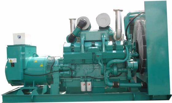
1.                   What is mean by the excitation of a generator?

Excitation refers to the creation and strengthening of the magnetic field by the passage of direct current through the field coils. There are two methods by which a generator may be excited.
(a)    Self- excitation: The iron core of the field poles always retains a small amount of magnetism called residual magnetism. When a DC generator starts up from rest, the residual magnesium is sufficient to induce a small voltage in the amateur windings, and a correspondingly small current starts voltage is induced in the armature. The voltage thus goes on developing until it reaches the normal voltage.
(b)   Separate excitation: Here the field current is obtained from a separate source. An AC generator does not lend itself to self-excitation because the field windings require DC current, whole the amateur produces only AC. The most common arrangement employed top furnish DC supply for the field is to provide a separate excite which is nothing but a small self excited DC generator, coupled directly to the main generator shaft. This exciter furnishes the DC fields current of the main generator.
One of the modern methods employed in the case of small machines is to provide a metal rectifier to convert AC voltage generated by the amateur to DC to excite the field system instead f exciter.

2.       Are any special precautions necessary in paralleling of alternators?

Yes. The following conditions should be satisfied before they can be connected together.
(a)    The frequency of both should be identical.
(b)   The voltage of both must be the same.
(c)    The phase rotation in both machines should be the same.
(d)   Identical phase wire R.Y.B. should be connected together at the exact instant when there is zero phase different between them.
(e)   For satisfactory parallel operation the characteristics of the two machines should be similar.

3.       What is the effect for increasing or decreasing the excitation of an alternator when running in parallel with another?

As already stated excitation does not affect load sharing. Its only effect is to change the division of the reactive current. Consider two alternators running in parallel taking equal loads if excitation of No.1 machine is increased, it will take more of the lagging reactive current and No.2 machine will take less. Any inequality of excitation is equalized by a circulating reactive current passing from the over excited machine to the other. Therefore, the field regulator of the two machines should be adjusted, keeping an eye on the load current as well as the power factor meter on the alternator panel.

4.       What is an automatic voltage regulator and what is its function and why is it provided?

Due to rapid variations in the load from instant the voltage also fluctuates considerably because of the varying voltage drop in the armature circuit. To overcome this unsatisfactory feature automatic voltage regulators are usually provided to maintain the generator voltage reasonably constant in spite of the fluctuating load i.e., to increase the voltage when the load is high and reduce it when the load comes down.

There are several types of automatic voltage in use:
(a)    Brown Boveri regulator
(b)   Carbon pile regulator
(c)    Tirril voltage regulator

5.       If a generator fails to build up voltage when started or the voltage of the generator is too low what are the possible defects and how will you overcome them.

Some of the possible defects are given below.
1.)    Loss of residual magnesium.
2.)    Open circuit or loose connection in the exciter circuit also short circuited turns in field windings.
3.)    Reversed field windings.
4.)    Open or short-circuit in armature windings.
5.)    Excessive contact resistance on commentator due to incorrect grade of brushes or insufficient pressure or dirty commutator.
6.)    Incorrect position of brush.
6.       What indication and protective equipment is provided on the alternator panels?

A.)   Indicating instruments.
                                i.   Volt meter.
                              ii.   Ammeter with 3 position ammeter switch
                            iii.   Frequency meter
                             iv.   Power factor meter
                            v.   Synchorscope with synchronizing plug.

B.)    Protective device:
i.)      Overload relay

ii.)    Reverse power relay

iii.)  Earth leakage relay

C.)    Control devices

i.)      Excitor regulator

iv.)  Oil circuit breaker.